

Installation of Optical fibre Cable by Blowing / Jetting
Optical fibre cables for telecommunication applications have been installed in pipes/ducts for many years. The installation process is influenced by local conditions, local climate, customer's existing procedures, and customer requirements. There are two basic methods of cable installation in a preinstalled duct - pulling method and blowing method. The cable installation method is selected based on site conditions and the availability of machinery & resources. Table 1 shows a comparison between the two installation methods.
Comparison between Pulling and Blowing methods
Pulling methods
Blowing methods
Overall, the blowing method is preferred over the traditional pulling method due to savings in manpower & installation time and improved installation efficiency, particularly in longer ducts with multiple bends and undulations. In this application note, cable installation by blowing method and its best practices are explained.
Pulling methods
Cable installation by using high-speed air flow combined with additional mechanical pushing force is called as "blowing or jetting". Cable blowing is the process of installation of optical fibre cable into a pre-installed duct. Compressed air is injected into the duct inlet after a few hundred meters of cable is pushed into the duct. Compressed air flows at high speed through the duct and along the cable. The pushing force is applied mainly near the cable inlet by a pushing device. Standard optical fibre cables (like uni-tube, multi-tube, unarmoured & armoured ), microduct cables, and micro-ducts can be installed by using this method. It is possible to install microduct cable using the blowing method in continuous lengths of more than '1000 meters depending upon the duct route. There are two methods for blowing which are discussed below.
Method 1: High air speed blowing
This method requires pushing the cable with a tractor mechanism by traction rollers in a blowing
device for a few hundred meters and then introducing compressed air to make the cable inside the
ducts remain in floating condition, which reduces friction between the cable outer surface and
duct inner wall by reducing the area of contact as shown below in Figures '1 and 2.

Figure: 1
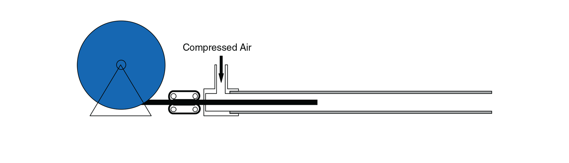
Figure: 2
Method 2: Push/Pull (Piston) blowing
In this type of blowing unit, an air-tight piston is attached to the front of the cable. The air
pushes this piston, and the piston "pulls" the cable as shown in Figure 3. Installers should be
aware that a pulling force exists in piston blowing, and the pulling force shouldn't cross the
maximum cable tension. This method is preferred for larger size ducts (32140mm and 42150mm) and
in "straight" trajectories to achieve longer cable blowing distance.
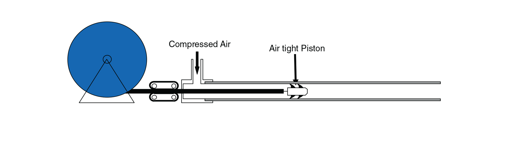
Figure: 3
Key Parameters of Blowing Method
The following three major parameters and their combined effects control how far a cable can be
blown in a duct.
Duct Fill Ratio (DFR)
The ratio between cable and duct size is known as the 'Duct Fill Ratio' or 'Fill Ratio'. There
are
two methods to calculate DFR.
a) The ratio between cross- sectional area of the cable and the inner space of the duct.
b) The ratio between cable diameter and duct inner diameter.
For optimum blowing performance DFR to be kept between 30 to 80%.
For conventional cable of diameter ≥ 10 mm: 30 to 50%
For micro cable of diameter 1-9 mm: 30 to 80%
Higher DFR helps to achieve longer blowing distance particularly in straight route. Higher DFR
also prevents cable buckling effect (cable forming a helix inside the duct) particularly for
cables with low stiffness. However, high DFR may result in shorter blowing distance in the route
having multiple bends. Therefore, an optimized DFR needs to be maintained to achieve the best
blowing
performance.
Coefficient of Friction (CoF)
Coefficient of Friction can be termed as the drag force (sliding friction) generated during
cable blowing due to area of contact between cable and duct inner wall because of the mass of
the
cable and gravity. CoF mainly depends on elevation, bending in duct route, undulations in duct
and properties of cable outer jacket materials. Generally stiffer materials like Polymide, high-
density polyethylene (HOPE) give better blowing results as compared to low density polyethylene
(LOPE) and flame retardant material like low smoke zero halogens (LSZH). CoF can be reduced by
using lubricants during the blowing of the cable. Blowing with lubricants increases efficiency
approximately by 50 %. CoF is also influenced by the quality of ducts i.e. inner wall material
of
duct (smooth & ribbed). Generally blowing distance in ribbed inner wall duct will be more as
compared to the smooth inner wall due to less area of contact between cable outer surface & duct
inner wall. Various factors that influence CoF, are summarized in Table 2.
| Component | Important Parameters/Characteristics | How to reduce CoF |
|---|---|---|
| Cable | Weight, Stiffness, Construction | Use of materials with low stiffness |
| Duct | Material of construction and design | Quality of duct (use of virgin HOPE materials), Inner surface (smooth/ ribbed), Low friction lining, Pre-lubrication |
| Duct Route | Straightness, Number of bends, Bend radii, Elevations, Cleanliness | Straight laying of ducts, no deformations and/or kinks and maintain minimum bend diameter >30 x Outer cable diameter (or as specified in cable design sheet) |
| Blowing Equipment | Temperature of compressed air, Presence of moisture in compressed air | Use of after cooler and water separator in a warm and humid climate |
| Lubricant | Quality and Quantity of lubricants, Method of application of lubricants | The lubricant material should not react with cable outer sheath ( don't use soap water, kerosene, diesel), Apply the right quantity by sponge or lubricator as suggested by the supplier |
Cable Stiffness or flexibility
The stiffness or flexibility of cable also plays an important role in blowing performance.
Stiffness
depends on cable design construction i.e. metallic or non-metallic, central tube or multi-tube,
outer jacket material, etc. Stiffer cable can achieve more blowing distance in straight
trajectory and flexible cable can achieve more blowing distance in difficult trajectories or
routes
with multiple bends and grading. Stiffer cable is preferable as it can blow fast through
undulation in ducts and avoids buckling of cable inside the ducts.
Cable Blowing Best Practices
a) Cable Crash Test
Prior to cable blowing it is important to perform the crash test to determine the maximum
pushing
force that can be applied on cable. Higher pushing force by tractor mechanism can damage cable
outer sheath and cable buckling at entry point. This test involves pushing the cable from the
blowing
head into 5 to 10 meters of a duct that is sealed at the other end. When the cable stops after
hitting the sealed end of the duct then the blowing head must stop pushing the cable such that
there
is no damage to the cable outer jacket and no cable buckling at the entry point. This process is
repeated with an increase
in push force until cable jacket damage is witnessed. The maximum permissible push force will be
the highest push force without any damage to the cable jacket. This test ensures that the
tractor will not damage the cable during installation in case of sudden stoppage of blowing.
b) Cable drum pay-off
This feature is very important in a blowing setup to ensure the cable is smoothly pushed inside
the
duct through the blowing unit. It is always recommended to use cable reel pay-off during cable
installation. The cable drum should be kept level to avoid the cable rubbing against the drum
flanges. The cable drum orientation should be such that the natural payoff direction is towards
the pulling direction. To eliminate possible cable contact with the ground, cable payout should
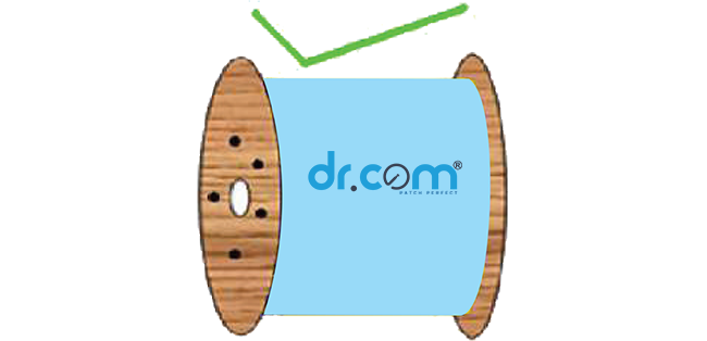
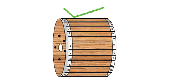
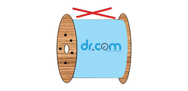
be from the top of the drum. Figure 4 shows a cable drum in a cable drum pay-off and figure 5
shows the do's and don'ts of cable unwinding.
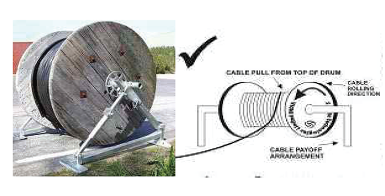
Figure: 4
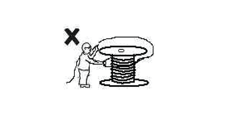
Figure: 5
Duct Integrity Test (DIT)
The purpose of DIT is to prove that the installed ducts are ready to use for blowing from one
manhole
to the other. DIT should be performed before blowing to avoid sudden surprises like missing
sections
of ducts, improper coupling, and kink and blockage in ducts. The DIT is carried out with the
help of compressed air and a suitable go-gauge sponge and mandrel of appropriate size, which is
pushed inside from one end with pneumatic pressure and is thrown outside from the other end. The
three steps outlined below should be performed to conduct integrity.
a) Step 1: Air pressure test
Duct continuity is verified by introducing compressed air from one end of the duct, and checking
if
air comes out from the other end of the duct. If no air emerges then the fault point has to be
identified
and corrected before proceeding further. Duct leakage is verified with compressed air by
attaching
the compressed air unit head to one end of the duct, and attaching the pressure gauge to the
other
end of the duct. Compressed air at a pressure of 10 bar is applied at the first end for 10 - 15
minutes
and air pressure drop at the other end of the duct is measured. If the pressure reading remains
the
same (not reduced to zero) at other ends for 5-10 minutes then there is no leakage in the duct.
If
the pressure reading drops to zero then there is leakage in the coupler (that joins two ducts),
and
the duct is punctured. Figure 6 shows a pressure gauge fixed at one end of the duct to monitor
air
pressure.
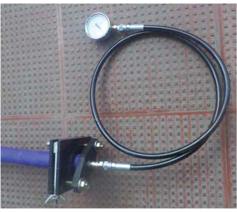
Figure: 6
c) Step 2: Shuttle test The kink in the installed ducts is located by shuttle test. A suitable shuttle of size 70-80% of the duct inner diameter is passed through the duct with the help of compressed air. If the shuttle comes out from the other end then the duct has no blockage and it is considered ready for cable blowing. If the shuttle does not come from the other end, then the duct is either kinked or blocked. To identify the blockage or kinked location, a transmitter is passed through the duct which will get stuck behind the shuttle and then the blockage point in the duct is tracked with the help of the receiver. The blocked portion of the duct is dug out and replaced. Figures 7 and 8 show a shuttle being inserted in a duct.
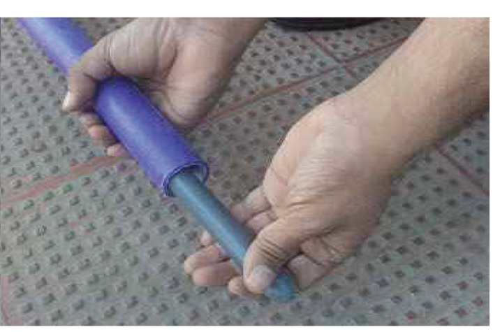
Figure: 7
Figure: 8
d) Step 3: Sponge Test Very often mud and water are found inside an underground duct. In this test, a sponge double the size of the duct inner diameter is passed through by compressed air to clean the duct. Figures 9 and 10 show a sponge being inserted into a duct.
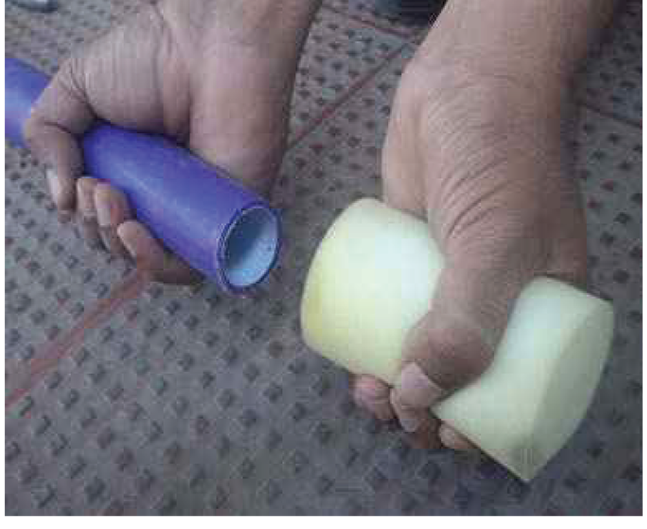
Figure: 9
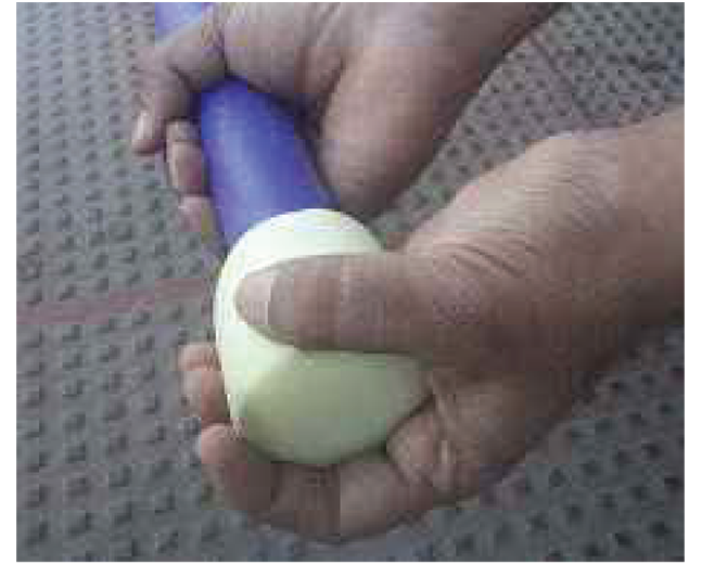
Figure: 10
A metal cap is fixed at the head of cable as shown in figure 11, to seal the cable end so that jelly or other elements of the cable will not damage the duct inner wall and cable blowing will be smooth.
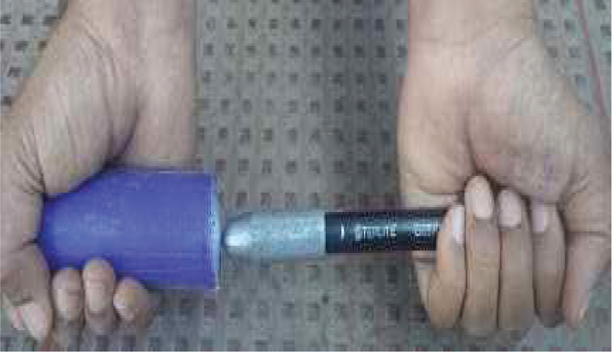
Figure: 11
Safety Procedure
This document provides the guidelines for handling, transportation, and storage
of
Optical fibre cable drums. These guidelines can apply to all 'Outside Plant Optical fibre
Cables'. This document provides information for the handling various reels/drums at various
places from receiving in stores to shipment to the site for installation.
Proper handling of cable reels/drums decreases the probability of accidental damage to cable,
material & personnel. All-optical fibre cables are sensitive to damage during handling, storage,
and installation. Such damage can degrade cable performance to the extent that replacement
becomes necessary.
Optical fibre Cable is a valuable product. If handling is not done properly, the drum and in
turn the cable may get damaged. At times, the damage might not be discovered until the
installation
process, when repairing the cable gets extremely difficult and also expensive.
There are a number of key safety issues that are important to keep in mind while handling the
Optical fibre Cables as follows:
1. Keep the cable drum/reel protected with outer covering till the time it is used at the
site.
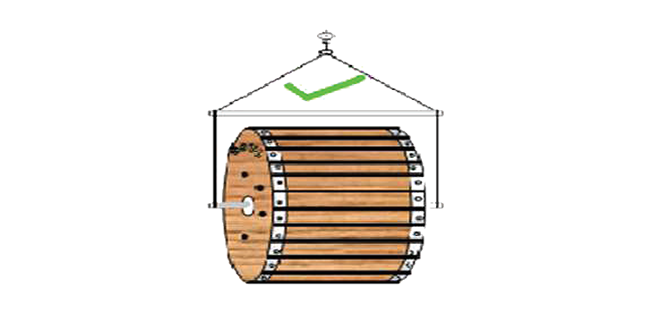
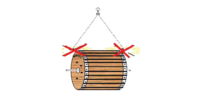
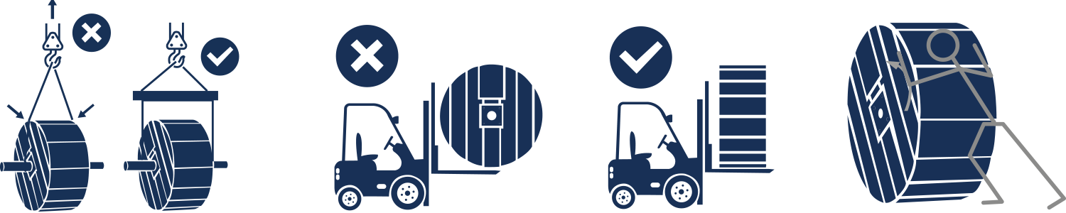
2. Lift the drums without damage
When lifting the drum; use a shaft through the center of the drum and a the spreader beam. In case spreader is not used the rope may damage the flanges of the drum which can cause cable damage.
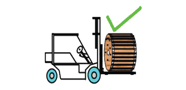
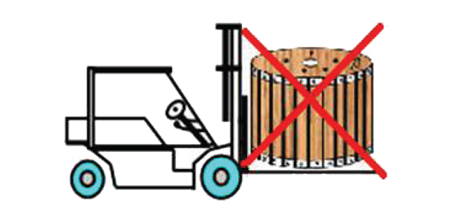
3. Handling with Forklift
Ensure the drums are moved in an upright position and the fork must be longer than the width of the drum. When moving the drums, tilt the truck mast so that the drum remains in the fork and the points don't touch the ground. Raise the forks of the forklift at least 6-8 inches from the ground surface. Don't release the forks until the truck has stopped completely. Keep sufficient space between the drums so that forks don't damage the other drum.
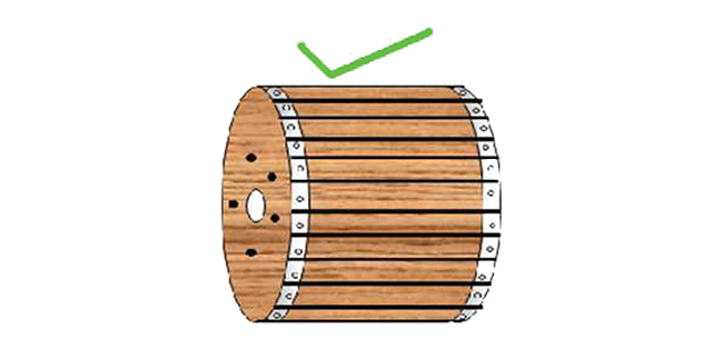
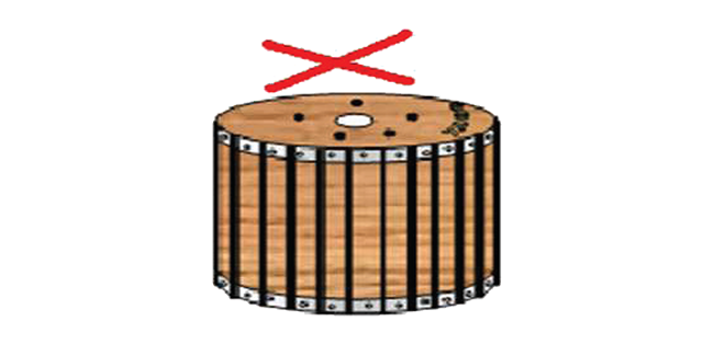
4. Keep the Drum in an upright position
The drum is designed to be handled in an upright position. It may not sustain if lifted laying flat. When stored in an upright position, the cable-layers do not get entangled during uncoiling.
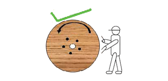
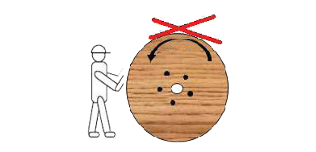
5. Roll the drums only as per the direction marked on the drum flanges
When the drums need to be rolled due to some reason, always roll the drums in the direction of the arrow marked on the drum flanges. This way the cable over the drum will not loosen. However, this does not mean that the drum can be rolled freely for any distance. Limit rolling distance to 5-10 meters. Once placed in position, use a proper stopper to prevent drums from rolling.
6. Drum transportation, Unloading, and Storage

A) During transportation, the cable drums should not be kept in a Flat position; it crushes down the layer of the cable, resulting in fibre breakage.

B) The cable drums should always be kept in an upright position and be tied with a Chain or Belt with wooden blocks that should be kept in between the flanges of each drum to avoid any jerks/ movements during transportation.
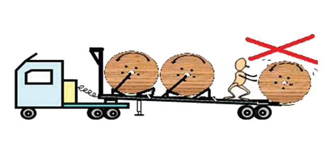
C) While unloading the truck it is important that the cable drum should not be dropped directly on the floor. The weight of the Drum & cable may cause deflection of Drum flange resulting in flattening, deformation, or damage to the cable.
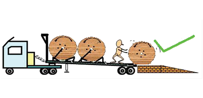
D) The drum must be rolled from a truck on to receiving platform, which should be at the same height as the tailgate of the truck. An alternate is to use a forklift to unload drums from truck.
Note: If inclined ramps are used, roll the drums over it; but don't allow them to roll out of control. Roll each drum away from the bottom of the ramp before handling the next drum.
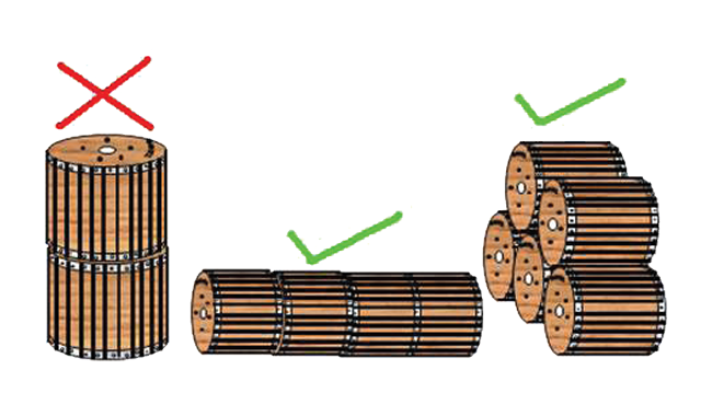
E) The drums should always be stored in an upright position. Storage of drums in an alternative position can lead to winding defects.
F) If storage place is limited and it becomes necessary to stack, then stack the completely wrapped on their flanges. Stacking is allowed only for the drums whose flange diameter is 1250mm or less. Do not store drums on Flat flanges
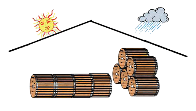
G) Optical fibre cables are winded on wooden drums. Due to the environment surrounding, the drum gets degraded over a period of time. To avoid such degradation in the wood during its storage period, in-house storage is recommended. If drums are stored outside, storing surface should be hard & no moist soil should be in contact with wood, this avoids the generation of harmful insects responsible for wood degradation. During heavy rain, the drums should be closed by polythene to keep the Drum moisture content around 18% to 25%. Copyright
Standard Method & Procedure for Laying Armoured Cables
Below are some standard methods & procedures for laying armoured cables. This will be the solution for the below problem observed during laying.
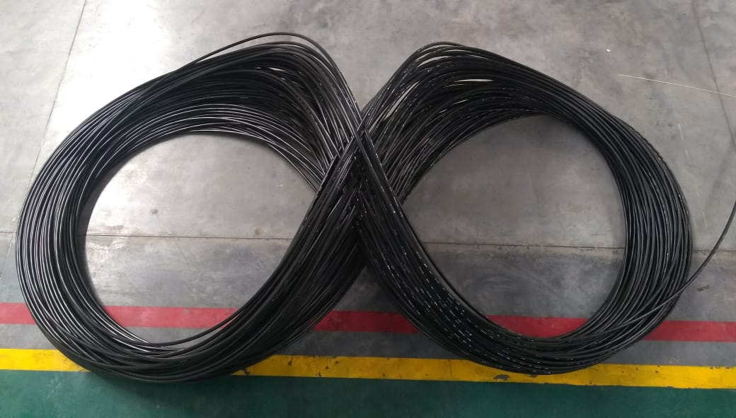
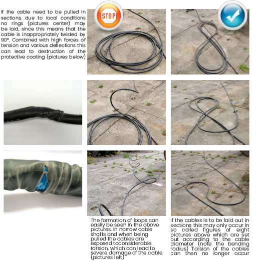
1) Method for uncoiling cable from cable reel:
The cable should be uncoiled from the cable reel and shall be arranged in a figure 8 (Eight) shape. The dimensions of each loop of the figure 8 shall be maximum 2 mtrs. This method will avoid cracking of sheath and also avoid damages in the cable while uncoiling cable from the reel. Please refer to the image below for your reference.
2) Minimum Bending parameters
3) Installation Guidelines as below.
Buried Installation of Optic fibre Cable
A buried cable is a kind of communications cable which is specially designed to be buried under the ground without any kind of extra covering, sheathing, or piping to protect it. This cable is built to specific tolerances to heat, moisture, conductivity, and soil acidity. Unlike standard telecommunications cables, which have only a thin layer of insulation and a waterproof outer cover, Buried Cable may consist of multiple layers of sheathing or jacketing, reinforced by metallic-banded, shock-absorbing gel, wrapped thread-fortified waterproof tape, etc. This Applications Note describes the placement of optical cables as buried cable in the outside plant portion of the communications network.
Introduction
A buried plant is usually placed into a narrow trench or plowed directly in the ground. Sometimes a fibre cable is placed in an open trench with several empty sub-ducts for use when future service demands require more cable infrastructure.
A general description of placing fibre cables will be presented in this Note. The Direct buried cable placing methods described in this document are intended as guidelines. National, state, local, and corporate specifications, regulations, and industry recommendations normally take precedence over these. It is impossible to cover all the conditions that may arise during a placing operation. Individual company practices for placing fibre optic cable should supersede any conflicting instructions in this document whenever they do not exceed the cable's optical and mechanical performance specifications. This note is not intended as a replacement for instructions or operations described by the manufacturer's procedures for the materials and equipment being used.
Advantages of Buried Plant
The construction of a buried plants is popular because it provides three major
advantages over
other types of communications plant construction when used in properly-suited areas.
a. It provides a fast installation procedure.
b. It is economical both in initial investment in infrastructure and it provides good
flexibility
in being able to place the new plant in a more timely manner to closely match new service
demands.
c. It is the least disruptive to surface conditions along the right-of-way.
Buried construction is well suited for use in the following conditions:
Precautions
1) Cable Handling
All-optical cables are sensitive to damage during shipping, handling, and installation. Some of the important parameters that need special attention during cable installation are:
a. Cable Bending radius: Optical fibre cables are designed with a minimum bending
radius
and maximum tensile strength. The cable should never be bent below its minimum bending
radius. Doing so can result in bending losses and/or breaks in the cable's
fibres. Generally
the minimum bending radius of a fibre cable under load is 20 × D, where D is the diameter
of the cable the minimum bending radius of a fibre cable under no load is 15 × D.
b. Cable Placing Tension: Optical cables are designed with maximum tensile
strength. The
cable should never be loaded beyond its maximum tensile strength. Exceeding this value
provided by Sterlite in the Cable Data Sheet / Specification, can alter cable and fibre
performance and shorten its service life.
2) LED and Laser Precaution
LED and Laser beams used in testing fibre optic cable and transmission systems are invisible to the human eye and can seriously damage the eye. Viewing these beams directly may not cause any pain and the iris of the eye does not close automatically as it does while viewing a bright light. As a result, the eye may not react to protect itself, causing serious damage to result to the retina.
3) Material Safety
fibre optic splicing and termination processes often use various chemical cleaners. The safety instructions developed for these substances should be followed. If there is confusion in the usage of these products, ask their manufacturer for a Material Safety Data Sheet (MSDS). Remember the following instructions while working with these chemicals.
1. Always work in well-ventilated areas.
2. Avoid skin contact with these cleaning materials as much as possible.
3. Avoid using chemicals that cause allergic reactions.
4. Isopropyl alcohol, used as a cleaner, is flammable and should be handled carefully.
Note: Warranty for cable will be applicable if the cable is laid as per standard procedure.
CATV OPTICAL FIBRE CABLES
Handling & Installtion Guidelines
Installation Technique :